AVC-485 Automatic Valve Controllers
AVC-485 Product Manual – click to download (Note: Requires the Adobe Acrobat Reader)
Description
The AVC-485 Automatic Valve Controller is designed to permit either manual or fully automatic operation of diffusion, turbo, or cryopumped high vacuum pumping systems. Provision is made, or can easily be added by the customer, for a variety of interlocks to protect the vacuum system from improper sequencing of values or the presence of unusual but damaging conditions.
The AVC-485 is powered from a 115 volt, 2 amp source and will handle the three basic electropneumatic vacuum valves (roughing, foreline, high vacuum) and a solenoid vent valve in any vacuum system. Switchable between fully automatic or manual control.
Time delay, for sequential automatic valve operations is preset. Settings can be changed to match a customer’s requirements.
A clear and bold schematic of a typical system is on the front panel to assist in tracing the function being performed. In the automatic mode, LEDs on the schematic indicate valve status.
The panel meter indicates the station pressure in the chamber and at the foreline or regen line. The sensors are the highly reliable and stable GT-034 thermistor tubes.
Operator-Selectable Phases – Pressing the system stop button closes all vacuum valves except the foreline valve on Diffusion/Turbo pump systems, putting the system in a standby condition. Pressing the system vent button puts the chamber in the standby condition and then opens the chamber vent valve. The vent valve is closed automatically after a preset time to conserve backfill gas.
Features
- Easily set controls simplify calibrations of trip points of fore-pressure and vacuum chamber pressure circuits
- Internally switchable for use with Diffusion/Turbo Systems or Cryo pump operation
- Relay trip point settings by means of internally mounted potentiometer
- Adjustable 1-15 minute auto vent stop output
- Capable of interlocking with external controls
- Tamper-resistant AUTO/MANUAL mode
- RF filtered and shielded
- Easy service – all parts are readily accessible
- Low profile cabinet-suitable for direct rack mounting
Mode Selection
A screwdriver-actuated switch is used to select Auto or Manual Mode.
Manual Mode
This mode is used when performing maintenance or when operating under exceptional conditions. All valve functions are controlled by the operator alone, using the pushbutton switches. Safety interlocks are inoperative.
Automatic Mode
In this mode, the controller programs the vacuum system through the roughing and high-vacuum phases at the touch of the system start button.
When switched to the automatic mode, the controller sets the system in a safe operating condition regardless of the position of the manual pushbuttons.
When switched to the manual mode, the controller will not latch in to the manual mode until all manual pushbuttons are in the off (valve closed) position.
These interlocks prevent inadvertent errors by the operator and protect the system during mode changes.
Safety Features
Valves are operated in response to system pressure instead of time. System malfunctions such as leaks, failure of the high-vacuum valve to seal, pump failures, etc. will cause the system to go into the system stop condition.
Gauge Specifications AVC-485
Power Input: 115 or 230 VAC, 50/60 Hz
Fuse type and rating: 2 amp 3 AG for 115V service, 1 amp 3 AG for 230V service
Output to energize valves: same voltage as AC line (valve solenoids must operate from same voltage as AC lines)
Valve solenoid current requirements: Typical inrush current 0.3 amps
Typical holding current: 0.1 amps
Maximum allowable current: 2 amps
Time delay adjustment range: all valves 3-20 seconds; auto vent stop 1-15 minutes; external control 5-20 seconds
Range of pressure responsive control circuits: 0-1000 milliTorr
Trip span (differential between turn-on and turn-off): 0-25% of meter scale length
External control relay drive: 5 VDC, 10 milliamps
Pressure sensor tubes (for recorder use): GT-034
Dimensions front panel: 3-1/2″ high, 19″ wide
Chassis depth: 8″
Ordering Information
AVC-485 – 115VAC – 50/60Hz, includes 10′ cable & 2 (034) tubes – Part Number 285862
AVC-485 – 115VAC – 50/60Hz, includes 25′ cable & 2 (034) tubes – Part Number 285862-1
GT-034 Thermistor tube – Part Number 277289
Cable 10′ – Station 1 – Part Number 286204-1
Cable 15′ – Station 1 – Part Number 286204-2
Cable 25′ – Station 1 – Part Number 286204-3
Cable 50′ – Station 1 – Part Number 286204-4
Cable 100′ – Station 1 – Part Number 286204-5
Cable 10′ – Station 2 – Part Number 286205-1
Cable 15′ – Station 2 – Part Number 286205-2
Cable 25′ – Station 2 – Part Number 286205-3
Cable 50′ – Station 2 – Part Number 286205-4
Cable 100′ – Station 2 – Part Number 286205-5
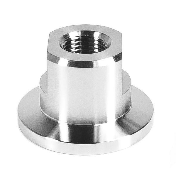
Vacuum Port Adapters
KF-16 to 1/8″ FPT KF – Part Number 500230-16
KF-25 to 1/8″ FPT – Part Number 500230-25
KF-40 to 1/8″ FPT – Part Number 500230-40
KF-50 to 1/8″ FPT – Part Number 500230-50
CF-16 to 1/8″ FPT – Part Number 500231-1
CF-35 to 1/8″ FPT – Part Number 500231-2
1″ hole mount to 1/8″ FPT – Part Number 500236